
India is seeing massive investment and growth in the PCB manufacturing sub-industry. June 27, 2026 saw the start of construction for two major PCB manufacturing projects to the tune of INR 6750 crore in Imported Printed Circuit Boards worth Rs 40,000 crore to be manufactured in Yamuna City, Jewar in Uttar Pradesh. What are PCBs? Why are they important? Let us learn more about both of these from the beginning.
Printed Circuit Boards
A printed circuit board is the nervous system and skeletal system of your electronic appliance, wrapped into one. The nervous system connects your brain to your organs and muscles using nerves to send signals and the skeletal system provides protection and structure to your organs. A PCB has copper traces to connect the components to other components. It provides the mechanical stability for implementing it in the real world.
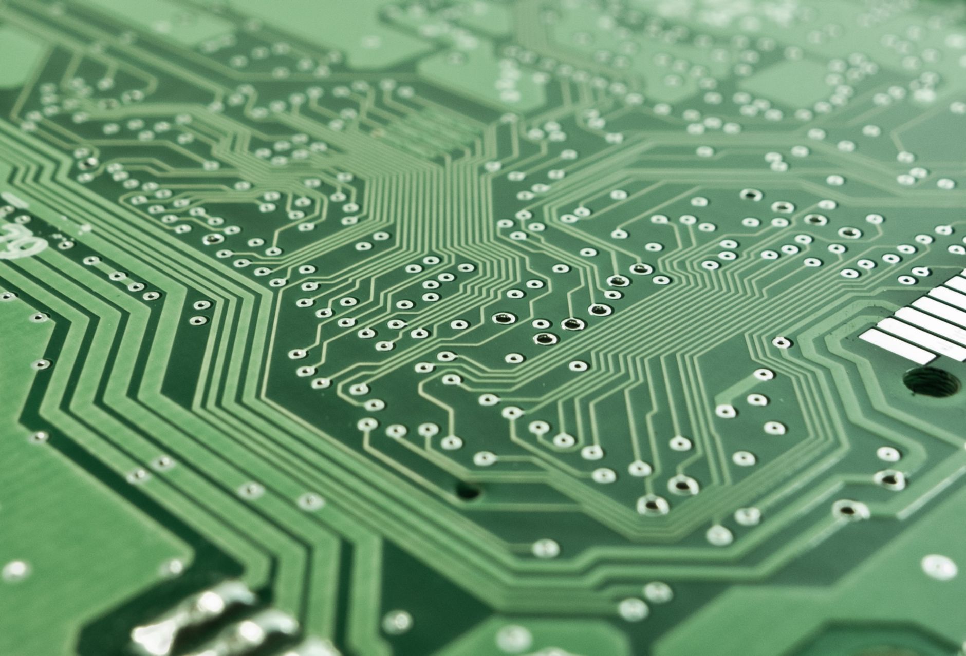

The most common PCB base material is a single or multi-layer sheet of copper and insulating material. PCBs can be rigid or flexible, flexible PCBs are used in curved televisions, foldable smartphones, wearable technologies and the like. You can open your TV remote, laptop backpanel, or any electronic device and you will find a big board with small black parts, the small black parts are electronic components which are soldered on the PCB.
THT versus SMT
Electronic components come in two different styles of output pins. One contains long pins protruding out from the device which needs holes on the circuit board and the other requires a small flat pad to make contact. Components requiring holes are put in the category of through hole technology (THT), and components with pads are mounted and soldered using surface mount technology (SMT).


SMT components are very small compared to THT components and are very useful for circuit miniaturization. Circuits which require low power and high information and/or signal speed favour SMD components. THT components are cheaper and, in most instances, tolerate higher power. There is no clear and straight answer for which one is better since both cater to different applications.
Workflow: schematic to circuit board
Before the circuit board, we need to conceptualize the circuit in an easy to read and understand schematic using the widely accepted circuit symbols to create a circuit diagram. The process of laying out the components on the final PCB design becomes more convenient and reproducing the same circuit in a different board is more achievable.

Running the footprint assignment tool and a simple design rules check (DRC) on the schematic, we move on to the layout configuration of the components on the board.

KiCAD has a feature that allows you to visualize your circuit in a 3D render. Understanding the layout and its dimensions in 2D is tough, 3D view provides a very accurate visual to provide ease of layout modification. Do not forget to use it.


Finally we send the PCB design for manufacturing and get the circuit board in the mentioned time. PCB manufacturers usually have the option to either get components soldered in or recieve bare PCBs. I opted for a bare PCB since I needed to test the board with varying capacitors.

The big question of whether the board works must be lingering in your mind. Well I am happy to tell you that the board is stable till 60V DC since that is the maximum we tested it up to. We allowed the board to run for 10 minutes and it was stable throughout.

A video to show the output variations of the circuit.
Why are PCBs so important?
These boards and their manufacturing technology allows the world to run efficiently on electronics. Every electronic appliance needs an electronic circuit, without these boards the entire electronic manufacturer would come to a standstill. There is no practical alternative to PCBs; they are the only reliable and economical way to mechanically support and electrically interconnect components. From smartphones, tablets, computers, medical equipment, automobiles, industrial automation systems, civil power supplies and telecommunications infrastructure to aerospace and defense applications, PCBs form the foundation of virtually every modern electronic device. Their importance extends beyond convenience—they allow compact, high-speed, reliable, and mass-producible electronic systems, making them indispensable to today’s technology-driven world.
Existing and upcoming manufacturers and projects
India has an established industry for low to mid volume PCB manufacturers. Some examples of these are:
- PCB Power in Gandhinagar, Gujarat;
- India Circuit in Noida, Uttar Pradesh;
- Sulakshana Circuits Ltd. in Pune, Maharashtra;
- Ascent Circuits in Hosur, Tamil Nadu;
- Genus Electrotech in Neemrana, Rajasthan;
- some more companies: fs-pcba
Upcoming projects in India will tackle the demand for commercial and large-scale manufacturers.
- Syrma SGS Technology in Naidupeta, Andhra Pradesh;
- Kaynes Circuits India in Oragadam, Tamil Nadu;
- ASCENT-K Circuit in a joint venture with South Korea’s KCC in Jewar Uttar Pradesh;
- Amber Enterprises in Jewar, Uttar Pradesh;
- Vital Electronics in Maharashtra;
- and many more which can be found in the above links.
Frequently Asked Questions (FAQ)
Ques: What is a bare/blank PCB?
It contains only the copper traces, pads, and insulating substrate. It does not have any electronic components mounted on it and serves as the foundation for assembling an electronic circuit. A blank PCB is another term for a bare PCB. It refers to a fabricated circuit board before any components are soldered onto it. The terms “blank PCB” and “bare PCB” are often used interchangeably.
Ques: What is a footprint in PCB design?
It is the physical layout on a PCB that defines where an electronic component will be mounted. It specifies the size, shape, pad locations, and spacing required to correctly solder the component onto the board.
Ques: What is DRC in PCB design?
It is an automated verification process used in PCB design software to identify errors such as insufficient trace spacing, incorrect hole sizes, overlapping components, and other violations of manufacturing design rules.
Ques: What is the full form of THT?
THT stands for Through-Hole Technology. It is a PCB assembly method in which component leads are inserted through holes drilled in the PCB and soldered on the opposite side, providing strong mechanical connections.
Ques: What is the full form of SMT?
SMT stands for Surface Mount Technology. It is a manufacturing technique in which electronic components are mounted directly onto the surface of a PCB without requiring through-holes.
Ques: What is the difference between SMD and SMT?
SMD (Surface Mount Device) refers to the electronic component itself, while SMT (Surface Mount Technology) refers to the manufacturing process used to mount those components onto a PCB. In simple terms, SMD is the component, whereas SMT is the assembly technique.
Ques: Which one is better, THT or SMT?
Neither technology is universally better. THT offers greater mechanical strength and is preferred for high-power or mechanically stressed components. SMT enables smaller, lighter, and more densely packed circuits, making it the preferred choice for most modern electronic devices.
Ques: What is the difference between rigid and flexible PCBs?
A rigid PCB is made from a solid substrate and cannot be bent after fabrication, making it suitable for most electronic products. A flexible PCB, on the other hand, is manufactured using flexible materials such as polyimide, allowing it to bend or fold, which is ideal for compact and portable electronic devices.

Leave a Reply